DC–18 GHz SP6T Terminated RF Switch (24 V, TTL, Indicators)
ERS-0000-18000-SP6T-24P-MOD-A
DC–18 GHz · Terminated SP6T · 24 V control · TTL-compatible inputs · Indicators
Compact electromechanical SP6T coaxial RF switch for routing RF signals up to 18 GHz. Terminated output ports (absorptive throws) reduce reflections on unselected paths, while the common port is reflective. 24 V control with TTL-compatible one-hot channel inputs (CH1–CH6) and indicator outputs.
Specifications subject to change without notice as part of continuous improvement.
Overview
Highlights
- Electromechanical SP6T routing, DC–18 GHz
- Terminated output ports (absorptive throws); reflective common port
- Low insertion loss: 0.30–0.50 dB max (band dependent)
- High isolation: 60–70 dB min (band dependent)
- 24 V control with TTL-compatible one-hot channel inputs (CH1–CH6) and indicators
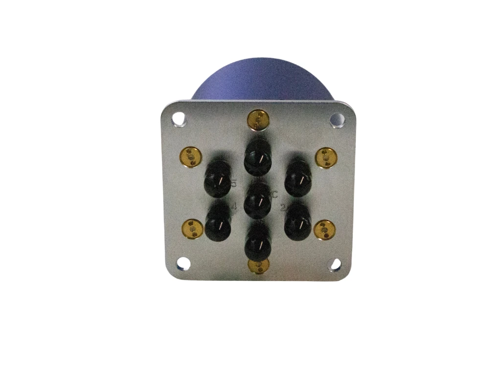
- 2.92 mm RF connectors (common + 6 throws)
Integration notes
- Provide a stable 24 V control supply sized for reset/inrush current (up to ~1.2 A DC @ 20 °C).
- Drive the channel lines as one-hot (assert only one of CH1–CH6 at a time).
- Connect Indicator COM to GND and read indicator pins as closures for the active channel.
- Terminate unused RF ports with 50 Ω for best repeatability.
- Follow standard ESD precautions during handling and integration.
Applications
- Automated Test Equipment (ATE) / automated RF routing
- Lab switching matrices and RF test benches
- Broadband measurement setups (terminated idle paths)
- Receiver path selection and signal distribution
Key specifications
| Frequency range | DC – 18 GHz |
|---|---|
| Insertion loss | 0.30 – 0.50 dB max (band dependent) |
| VSWR (input/output) | ≤1.3 – 1.5 :1 max (band dependent) |
| Isolation | 60 – 70 dB min (band dependent) |
| Switching time | ≤15 ms max |
| Average power handling | 27 – 45 W max (band dependent) |
| Control | 24 V supply, TTL-compatible one-hot (CH1–CH6) + indicators |
| Operating temperature | −45 °C to +65 °C (standard) |
Specifications subject to change without notice.
Control
24 V control (CH1–CH6)
Control is via TTL-compatible one-hot channel inputs (CH1–CH6). J0 is the common RF port. J1–J6 are routed outputs (throws). Indicators provide closures to Indicator COM for the active channel.
Quick start
- Terminate unused RF ports with 50 Ω (recommended).
- Apply control supply: 24 VDC within specification.
- Assert exactly one channel line (CH1–CH6) to select the desired output path.
- Optionally monitor the selected channel via indicator closures to Indicator COM.
- Apply RF at low power first, then operate within rated average power limit.
Drive only one channel line at a time (one-hot). Avoid floating inputs.
Channel map (CH1–CH6)
CH1 |
J0 → J1 |
|---|---|
CH2 |
J0 → J2 |
CH3 |
J0 → J3 |
CH4 |
J0 → J4 |
CH5 |
J0 → J5 |
CH6 |
J0 → J6 |
Example wiring notes
Control supply:
+24V (drive supply)
GND  (return)

Channel selection:
CH1..CH6 = one-hot selection

Indicators:
Connect "Indicator COM" to GND.
Read indicator pins as closures for the active channel.
For best RF repeatability, terminate unused ports with 50 Ω loads.
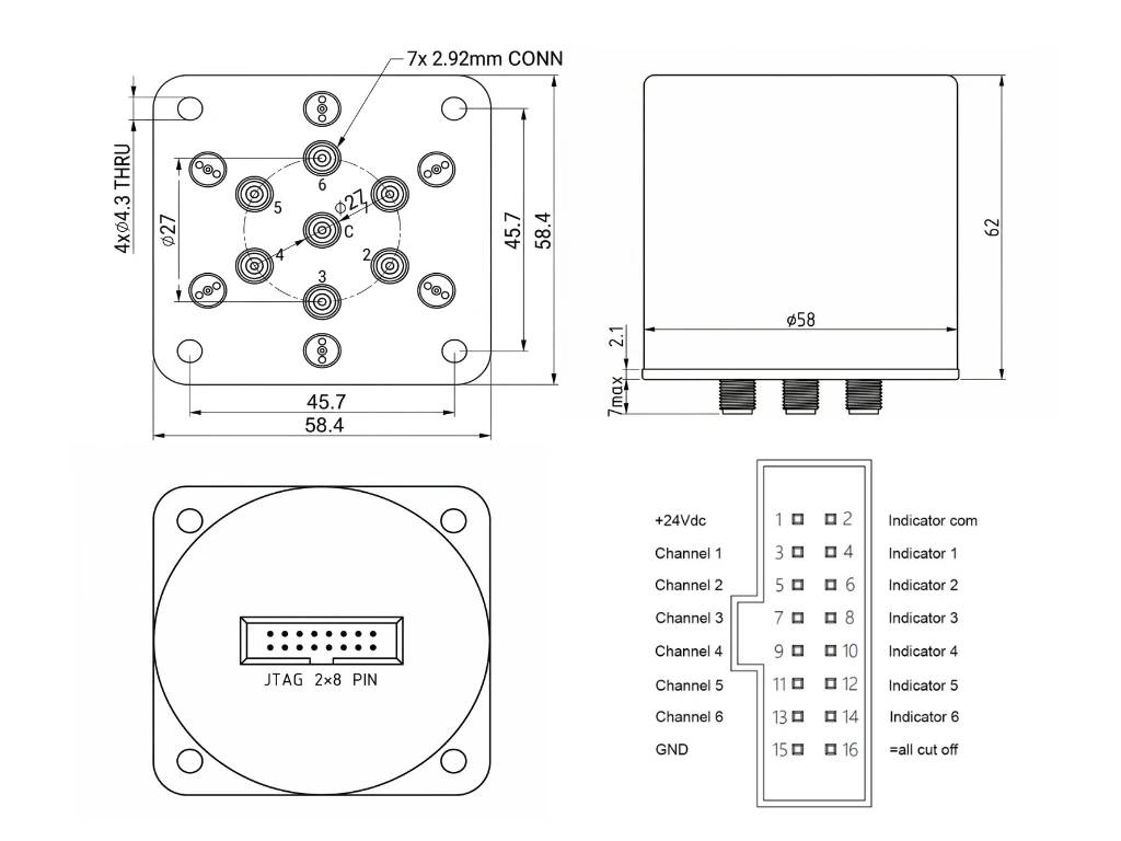
Mechanical
- Outline drawing and pin legend: see datasheet (downloads)
- Protection level: IP63 (as specified)
- Life: ≥ 5,000,000 cycles (minimum)
- Terminated outputs for reduced reflections on idle paths
- RF connectors: 2.92 mm (common + 6 throws)
- Control interface: DIP-DC 2×8 header (24 V, CH1–CH6, indicators)
- Indicator outputs: closure to Indicator COM for active channel
- ESD precautions recommended during handling and integration
Outline drawing