
DC–18 GHz SP6T Terminated RF Switch 24 V TTL Control with Indicator Outputs
DC–18 GHz · Terminated SP6T · 24 VDC · TTL control · 2.92 mm
Terminated electromechanical SP6T coaxial switch for broadband RF path selection. Six absorptive throw ports, a reflective common port and indicator outputs support automated test and integrated routing systems.
Pricing and availability may change without notice.
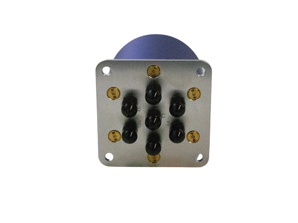
Overview
Highlights
- Electromechanical SP6T switching from DC to 18 GHz
- Six internally terminated output ports with a reflective common port
- 2.92 mm RF connectors for six throws and one common port
- 24 V control supply with TTL-compatible channel selection
- Indicator contact outputs for the active channel
- Switching time of 15 ms maximum
System integration
- Designed for 50-ohm RF systems
- One-hot channel selection is recommended
- Apply the control supply before asserting a channel input
- Apply RF only after mechanical switching is complete
- Hot switching is not recommended unless specifically qualified
- Use controlled connector torque and provide coaxial-cable strain relief
Applications
- Automated Test Equipment and automated RF routing
- Laboratory switching matrices and RF test benches
- Broadband measurement systems requiring terminated idle paths
- Receiver-path selection
- Signal distribution and integrated RF routing
- Instrumentation, defense and professional RF systems
Key specifications
RF performance
| Frequency range | DC–18 GHz |
|---|---|
| Configuration | Electromechanical SP6T |
| System impedance | 50 Ω |
| Unselected throw ports | Internally terminated, absorptive |
| Common port | Reflective when no channel is selected |
| DC–6 GHz | ≤ 0.30 dB insertion loss; ≤ 1.30 VSWR; ≥ 70 dB isolation; ≤ 45 W average power |
| 6–12 GHz | ≤ 0.40 dB insertion loss; ≤ 1.40 VSWR; ≥ 60 dB isolation; ≤ 40 W average power |
| 12–18 GHz | ≤ 0.50 dB insertion loss; ≤ 1.50 VSWR; ≥ 60 dB isolation; ≤ 27 W average power |
Control and reliability
| Control supply | 24 VDC |
|---|---|
| Control method | TTL-compatible one-hot channel selection with failsafe behavior |
| Control interface | DIP-DC 2×8 header |
| Drive current | ≤ 200 mA at 20 °C |
| Reset current | ≤ 1200 mA at 20 °C |
| Switching time | ≤ 15 ms |
| Operating life | ≥ 5,000,000 cycles |
Environmental limits
| Operating temperature | −45 to +65 °C |
|---|---|
| Storage temperature | −55 to +85 °C |
| Relative humidity | 5% to 85%, non-condensing |
| Protection level | IP63 |
| Shock, power off | 50 G, 11 ms, half-sine |
| Vibration, power on | 10 G RMS, 20–2000 Hz |
Control interface
The 2×8 DIP-DC interface provides the 24 V supply connection, six TTL-compatible channel inputs, six indicator contacts, Indicator COM, ground and an all-channels-off input.
Recommended operating sequence
Use a clean regulated 24 V supply and defined TTL input levels. Only one channel input should be asserted at a time.
- Ensure the required RF ports are correctly connected and terminated.
- Apply the +24 V control supply.
- Assert one channel input from CH1 to CH6.
- Allow mechanical switching to complete.
- Verify the selected path using the corresponding indicator contact if required.
- Apply the RF signal within the specified power limit.
For shutdown, remove the RF signal, de-assert the channel input and then remove the 24 V supply.
DIP-DC pin assignment
Pin 1
|
+24 VDC control supply |
|---|---|
Pin 2
|
Indicator COM |
Pin 3
|
CH1 channel-select input |
Pin 4
|
IND1 indicator contact |
Pin 5
|
CH2 channel-select input |
Pin 6
|
IND2 indicator contact |
Pin 7
|
CH3 channel-select input |
Pin 8
|
IND3 indicator contact |
Pin 9
|
CH4 channel-select input |
Pin 10
|
IND4 indicator contact |
Pin 11
|
CH5 channel-select input |
Pin 12
|
IND5 indicator contact |
Pin 13
|
CH6 channel-select input |
Pin 14
|
IND6 indicator contact |
Pin 15
|
Ground / control return |
Pin 16
|
ALL CUT OFF / all-channel inhibit |
Indicator outputs are passive contact closures to Indicator COM. Use suitable external pull-up resistors when monitoring them with logic inputs.
Mechanical
| Mounting footprint | 58.4 × 58.4 mm |
|---|---|
| Body diameter | Ø58 mm |
| Overall height | 62 mm from the mounting-plate face |
| Mounting holes | 4 × Ø4.3 mm through holes |
| RF connectors | 7 × 2.92 mm; six throws and one common port |
| Control connector | DIP-DC 2×8 header |
Mount the switch on a flat, rigid surface. Avoid connector side-loading and use the released drawing and STEP model when completing the mechanical integration.
Mechanical drawing
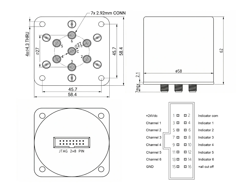
Reference outline showing the mounting dimensions, seven 2.92 mm RF connectors and the authoritative 2×8 control-pin assignment.