
Model: ERA-2400-2500-60W-32P-MOD-A
E-REON P/N: Z-000068
RF Power Amplifier Module, 2400–2500 MHz, 60 W, +32 V Compact 2.45 GHz ISM-Band RF Power Amplifier
2400–2500 MHz · 60 W CW nominal · 27 dB typical gain · +32 VDC · SMA female RF interfaces
Compact solid-state RF power amplifier module designed for continuous-wave operation in 2.45 GHz ISM applications. The module provides an enable input and an aluminium housing for mechanical and thermal integration.
2400–2500 MHz
60 W CW
27 dB Gain
+32 VDC
In stock
Frequency
2400–2500
MHz
Output power
60
W CW
Gain
27
dB typ.
Price:
€ 399
(excl. VAT)
•
Availability:
In stock
•
Typical lead time:
2 weeks
Pricing and availability may change without notice.
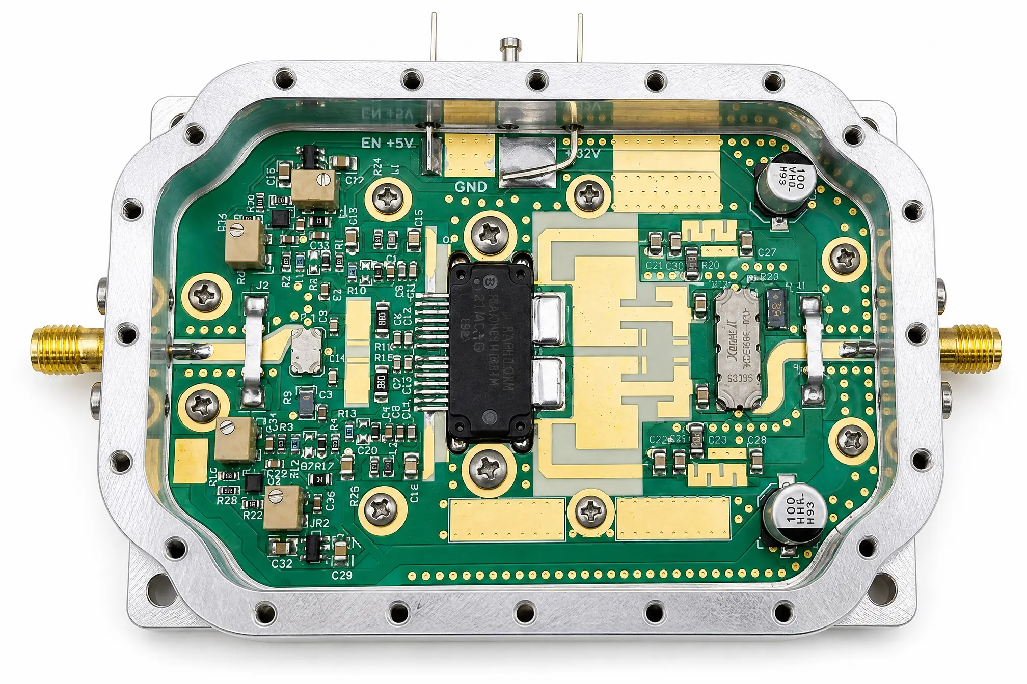
Overview
Highlights
- 2400–2500 MHz ISM-band operation
- 60 W CW nominal RF output power
- 27 dB typical small-signal gain
- ±1 dB typical gain flatness across the operating band
- Single +32 VDC main supply
- +5 V enable input for RF output control
Integration requirements
- Mount the module to a suitable heatsink or cold plate
- Use a stable DC supply with adequate current capability
- Operate with a properly terminated 50-ohm RF output path
- Use low-impedance grounding to the host system
- Verify thermal performance under the intended operating conditions
Applications
- 2.45 GHz ISM RF systems
- Industrial heating systems
- Plasma generation
- Laboratory RF sources
- RF driver and test systems
Key specifications
RF performance
| Frequency range | 2400–2500 MHz |
|---|---|
| Nominal frequency | 2450 MHz |
| RF output power | 60 W CW nominal |
| Small-signal gain | 27 dB typical |
| Gain flatness | ±1 dB typical |
| Nominal RF input drive | +22 dBm |
| RF impedance | 50 ohms |
| Operating mode | Continuous wave |
Electrical and interfaces
| Main supply | +32 VDC nominal |
|---|---|
| Enable input | +5 VDC nominal |
| RF input connector | SMA female |
| RF output connector | SMA female |
| DC and control interface | Pin terminals for enable, ground and main supply |
| Export classification | EAR99 |
Operating and thermal guidance
Operating practice
- Mount the module to its thermal interface before operation
- Connect the RF output to a suitable 50-ohm load or system path
- Apply the +32 VDC supply before enabling the amplifier
- Apply RF drive only after supply and RF connections are verified
- Remove RF drive before disabling and powering down the module
Thermal integration
- An external heatsink or cold plate is required
- Use an appropriate thermal-interface material
- Use a flat and clean mounting surface
- Forced airflow may be required for the final application
- System-level temperature monitoring is recommended
Mechanical
| Module dimensions | 93 × 65 × 20 mm, excluding connector protrusion |
|---|---|
| Mounting-hole spacing | 84 × 56 mm |
| Mounting holes | 4 × Ø3.4 mm |
| Housing | Aluminium 6061 with clear chromate finish |
| RF connectors | SMA female input and output |
| DC and control interface | Pin terminals |
| Cooling | External heatsink or cold plate through the baseplate |
Mount the module using suitable fasteners and thermal-interface material. Dimensions are provided for mechanical integration.
Mechanical drawing
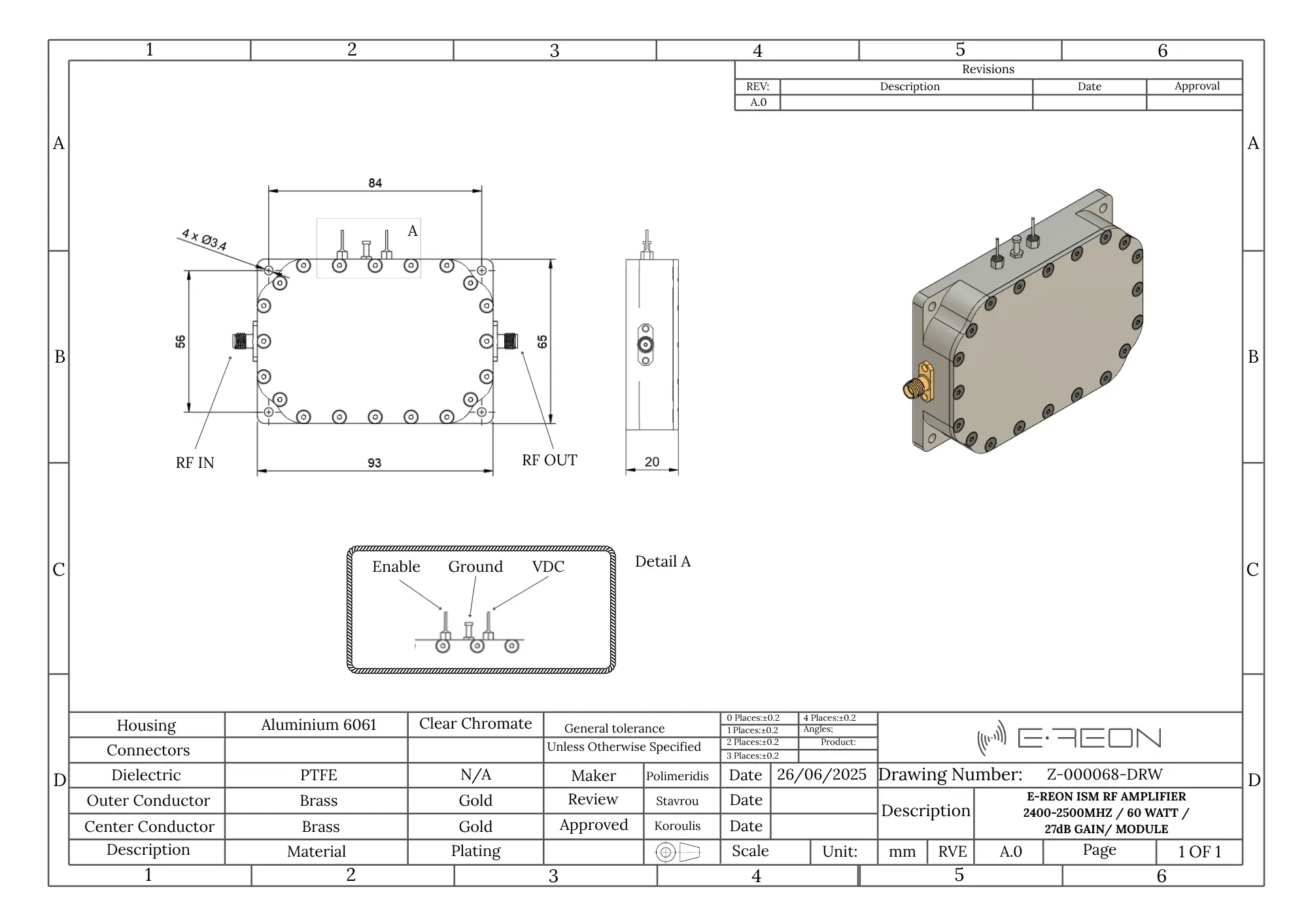
Reference outline drawing; dimensions are in millimetres. Confirm the released mechanical interface before completing system design.