Model: ERA-010060-20W-28P-MOD-A
|
E-REON P/N: Z-000045
RF Power Amplifier Module, 1–6 GHz, 20 W, +28 V
Wideband RF Power Amplifier with Integrated Monitoring
1–6 GHz · 20 W CW · 43–45 dB gain · +28 V · Integrated current & temperature sensors
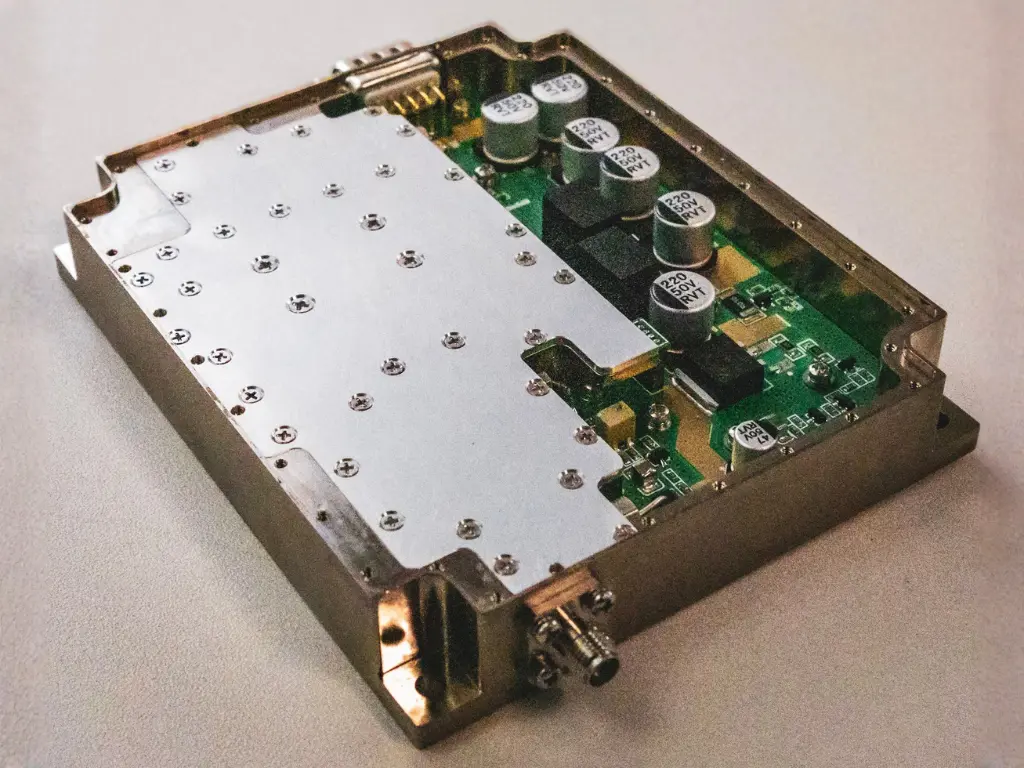
Wideband RF power amplifier module designed for CW and pulsed signals in the 1–6 GHz range. Integrated current and temperature sensors provide monitoring and safe system integration.
1–6 GHz
20 W CW
43–45 dB gain
+28 V
Usually in stock
Frequency
1–6 GHz
Output power
20 W
Gain
43–45 dB
Price:
€ 2300 (excl. VAT)
•
Availability:
Usually in stock
Pricing and availability may change without notice.
Overview
Highlights
- Wideband operation: 1–6 GHz
- Output power: 20 W (43 dBm)
- High gain: 43–45 dB with ±1.2 dB flatness
- Integrated current and temperature sensors
- 28 V single supply operation
Usage note
- External heatsink or cold-plate cooling is required
- Monitor VTEMP and VCUR during operation
- Verify load match before applying high output levels
- Follow the recommended bias sequencing before applying RF drive
Applications
- Radar systems
- Communication jammers
- Test instrumentation
- Broadband RF subsystems
Key specifications
| Frequency range | 1 to 6 GHz |
|---|---|
| Gain | +43 to +45 dB |
| Gain flatness | ±1.2 dB |
| Output power (CW, Psat) | 20 W nominal / 43 dBm |
| Nominal input drive level | 0 dBm nominal, +10 dBm max |
| Efficiency | 30% typical at Psat |
| Quiescent current (IDQ) | 1.5 A typ, 2 A max |
| Input VSWR | ≤ 1.5 |
| 2nd harmonic | -12 dBc typical |
| 3rd harmonic | -15 dBc typical |
| Spurious suppression | -70 dBc typical |
| OIP3 | TBD |
| Switching speed | < 50 µs |
| DC supply voltage | +28 VDC single supply |
| Absolute max supply voltage | +30 V |
| RF input power, CW (absolute max) | +10 dBm |
| Output VSWR (no damage) | 2:1 all phase angles |
| Export classification | EAR 99 |
Values at +28 VDC, 25 °C, ZS = ZL = 50 Ω unless otherwise noted. Specifications subject to change without notice.
Control & interface
DB-9 control connector
| Pin 1 | Vcc: +28 V DC power input |
|---|---|
| Pin 2 | Vcc: +28 V DC power input |
| Pin 3 | Vcc: +28 V DC power input |
| Pin 4 | GND: power ground |
| Pin 5 | GND: power ground |
| Pin 6 | GND: power ground |
| Pin 7 | VTEMP: temperature sensor output (10 mV/°C) |
| Pin 8 | VCUR: current sensor output (100 mV/A) |
| Pin 9 | PAEN: enable input (+3.3 V = ON, 0 V = OFF) |
Bias sequencing
- Apply +28 V supply to Vcc (pins 1–3 tied together)
- Ensure RF input signal is disabled during initial power-up
- Enable amplifier by setting PAEN (pin 9) to +3.3 V
- Apply RF input after the amplifier is enabled
Monitoring outputs
- VTEMP: Analog voltage proportional to temperature, 10 mV/°C
- VCUR: Analog voltage proportional to current, 100 mV/A
Mechanical
- RF input connector: SMA Female
- RF output connector: SMA Female
- DC / control connector: D-sub 9-pin male
- Cooling method: external heatsink / cold plate
- Weight: ≤ 2 kg
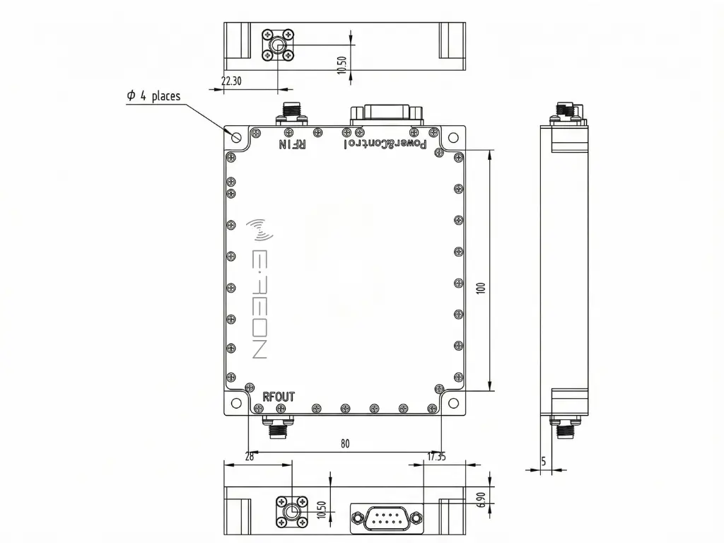
All dimensions are in millimeters unless otherwise specified. Mechanical drawing is provided for reference only.